English
 中文简体
中文简体 Español
Industry News
May 22,2026
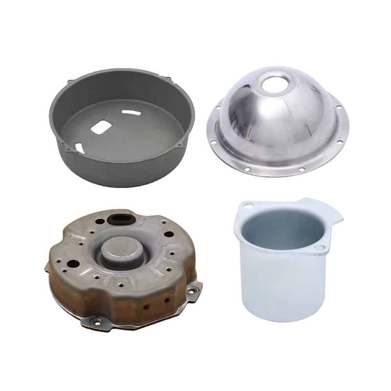
What are Metal Bending Drawing Parts?
Content
- 1 Bending Parts: Definition, Process, and Geometry
- 2 Drawing Parts: Definition, Process, and Depth Capability
- 3 Materials Used in Metal Bending and Drawing Parts
- 4 Tooling for Bending and Drawing: Dies, Punches, and Presses
- 5 Key Quality Parameters and Measurement Methods
- 6 Common Industrial Applications by Sector
- 7 Design Considerations for Metal Bending and Drawing Parts
- 8 Surface Finishing and Post-Processing Options
Metal bending drawing parts are sheet metal components produced by combining two cold-forming processes—bending and deep drawing—to create three-dimensional parts with precise angular features, curved walls, and hollow profiles from flat metal sheet stock. Bending deforms the metal along a straight axis to create angles, flanges, and channels, while drawing pulls the sheet over a die to form cups, boxes, and enclosed shapes with depth. The resulting parts retain the structural integrity of the original metal while achieving complex geometries that would be impractical or uneconomical to produce by machining from solid stock.
These parts are fundamental to modern manufacturing across automotive, aerospace, electronics, construction, and consumer goods industries. A single vehicle body, for example, contains hundreds of metal bending and drawing parts—from door panels and roof rails to bracket assemblies and fuel tank shells. Understanding what these parts are, how they are made, and what governs their quality is essential knowledge for engineers, procurement specialists, and manufacturers working with sheet metal components.
Bending Parts: Definition, Process, and Geometry
Metal bending parts are produced by applying force to a flat metal blank along a defined axis, causing plastic deformation that creates a permanent angle or curve. The process does not remove material; it redistributes it through controlled plastic strain. The outer surface of the bend is placed in tension while the inner surface is in compression, and the neutral axis—the plane experiencing neither tension nor compression—lies at approximately one-third to one-half of the material thickness from the inner surface, depending on the bend radius and material properties.
Primary Bending Methods
Several distinct bending processes are used in industrial production, each suited to different part geometries, material thicknesses, and production volumes:
- V-bending (air bending and bottoming) — The most common process; a punch presses the metal sheet into a V-shaped die. Air bending stops before the punch bottoms out, using the springback angle to achieve the target angle; bottoming drives the punch to contact the die, coining the material for higher accuracy (±0.5° typical for bottoming vs. ±1° to ±2° for air bending).
- U-bending — Creates channel-shaped or U-profile parts in a single stroke using a matching punch and die pair. Common for structural channels, cable trays, and enclosure frames.
- Roll bending — Three rolls progressively deform the sheet or plate to produce curved parts with large radii, such as cylindrical shells, conical sections, and curved structural members.
- Wipe bending (edge bending) — The sheet is clamped and a wipe die folds one edge over, producing flanges and return lips. Commonly used on press brakes for box and pan forming.
- Rotary bending — A rotating die rolls across the sheet surface to produce bends with minimal surface marking, preferred for pre-finished or cosmetically sensitive materials.
Minimum Bend Radius and Springback
Two critical parameters govern the feasibility and accuracy of every bent part. The minimum bend radius is the smallest radius to which a material can be bent without cracking on the outer tension surface; it is typically expressed as a multiple of material thickness (t). For example, mild steel (low-carbon) typically has a minimum bend radius of 0.5t to 1t, while high-strength aluminium alloys may require 3t to 5t minimum radius before cracking occurs.
Springback is the elastic recovery that occurs when the bending force is released, causing the part to open slightly from the intended angle. Springback magnitude increases with material yield strength and decreases with tighter bend radii. Process engineers compensate by overbending (using a die angle 2° to 5° tighter than the target angle) or by using bottoming and coining operations that minimise elastic recovery through through-thickness plastic strain.
Drawing Parts: Definition, Process, and Depth Capability
Drawing parts—more precisely, deep drawing parts—are produced by pressing a flat metal blank into a die cavity using a punch, forming a hollow three-dimensional shape with a closed bottom and open top. The process draws the flange material inward and downward into the die, thinning the walls slightly and thickening the flange as the metal flows. Drawing is the forming process behind beverage cans, cookware, automotive fuel tanks, medical device housings, and thousands of other hollow metal components produced in high volume.
The Deep Drawing Process Sequence
A complete deep drawing operation involves the following sequence:
- Blank preparation — A circular or shaped blank is cut from sheet stock. Blank diameter is calculated based on the target drawn part geometry and the material's drawing ratio limits.
- Blank holding — A blank holder (pressure pad) clamps the flange of the blank against the die face with controlled pressure, preventing wrinkling of the flange material as it is drawn inward.
- Punch descent — The punch descends, pressing the central area of the blank into the die cavity. The flange material flows inward under tension, forming the cup wall.
- Part ejection — The drawn part is ejected from the die using knockout pins or air ejection.
- Redrawing (if required) — If the required depth-to-diameter ratio exceeds what is achievable in a single draw, the part undergoes one or more redrawing operations, each reducing the diameter and increasing the depth incrementally.
Draw Ratio and Formability Limits
The limiting draw ratio (LDR) is the maximum ratio of blank diameter to punch diameter that can be achieved in a single drawing operation without tearing the part. For most low-carbon steels, the LDR is approximately 2.0 to 2.2, meaning a blank up to 2.2 times the punch diameter can be drawn into a cup in one operation. Aluminium alloys typically have LDRs of 1.8 to 2.0, while stainless steel ranges from 1.8 to 2.1 depending on grade. Parts requiring depth-to-diameter ratios that exceed the single-draw LDR are produced in multiple drawing stages with intermediate annealing if work hardening becomes limiting.
Materials Used in Metal Bending and Drawing Parts
Material selection for bending and drawing parts requires balancing formability (the ability to undergo the required deformation without cracking or wrinkling), strength in the finished part, corrosion resistance, and cost. The following materials represent the majority of production volume across industries:
| Material | Min. Bend Radius | Typical LDR | Springback Tendency | Typical Applications |
|---|---|---|---|---|
| Low-carbon steel (DC04) | 0.5–1t | 2.0–2.2 | Low | Auto body panels, enclosures, brackets |
| High-strength steel (HSLA) | 2–4t | 1.7–1.9 | High | Structural automotive, heavy equipment |
| Stainless steel (304) | 1–2t | 1.8–2.1 | Moderate–High | Food equipment, medical devices, sinks |
| Aluminium 1xxx / 3xxx | 0t–1t | 1.9–2.1 | Moderate | Cans, cookware, heat exchangers |
| Aluminium 5xxx / 6xxx | 1–3t | 1.8–2.0 | Moderate–High | Aerospace structures, automotive panels |
| Copper / brass | 0t–1t | 1.9–2.2 | Low | Electrical terminals, plumbing, decorative |
Tooling for Bending and Drawing: Dies, Punches, and Presses
The tooling system—the dies and punches—is the central determinant of part quality and production economics in bending and drawing operations. Tooling design must account for material springback, blank holder force, die clearance, punch corner radii, and lubrication strategy simultaneously.
Bending Tooling
Press brake tooling for bending consists of a punch (upper tool) and die (lower tool) mounted in a press brake machine. Standard European-style (Wila/Trumpf-compatible) tooling systems use modular punch and die segments that can be configured for different part lengths and profiles without dedicated custom tooling—significantly reducing setup costs for short-run or prototype production. For high-volume progressive die bending, dedicated hardened tool steel tooling is specified for each part geometry, with typical tool steel hardness of 58–62 HRC for working surfaces to resist wear over millions of cycles.
Drawing Tooling
Deep drawing dies consist of a punch, die ring, and blank holder, with precise clearance between punch and die (typically 10% to 15% greater than material thickness for single-draw operations) to allow metal flow without excessive thinning. Die corner radii are critical: too small a die radius tears the part at the die entry; too large a radius allows wrinkling. Die radii for steel typically range from 4t to 10t (four to ten times material thickness), with larger radii used for shallower draws and smaller radii for tighter geometry control in deeper parts.
Press Selection
Bending operations use press brakes (hydraulic, servo-electric, or mechanical) with tonnage matched to the material thickness and bending length. A common rule of thumb for V-bending mild steel requires approximately 8 tonnes of force per metre of bend length per millimetre of material thickness. Drawing operations use single-action or double-action hydraulic presses where the inner slide drives the punch and the outer slide controls blank holder force independently—a capability that is essential for consistent flange control in deep drawing.
Key Quality Parameters and Measurement Methods
Dimensional accuracy, surface integrity, and material property retention are the three primary quality domains for metal bending and drawing parts. Each is governed by specific measurement methods and acceptance criteria defined in engineering drawings and applicable standards.
Dimensional Tolerances
Angle tolerances for bent parts depend on the process: air bending typically achieves ±1° to ±2°, while bottoming and coining achieve ±0.5° or better. Linear dimensions on bent parts are affected by springback and are typically held to ±0.5 mm for general industrial parts and ±0.1 to ±0.2 mm for precision assemblies requiring close fit-up. Deep drawn parts are measured for wall thickness variation (typically ±10% of nominal wall thickness is acceptable), flange flatness, and overall height consistency.
Surface Quality
Acceptable surface quality for bending and drawing parts is defined by the absence of specific defects:
- Cracks at bend radii — indicative of insufficient bend radius relative to material ductility or excessive work hardening; inspected visually and by dye penetrant testing on critical components
- Wrinkling — compression wrinkles in the flange or wall of drawn parts; caused by insufficient blank holder force; evaluated against visual standards or surface profilometry
- Tearing — fracture at the punch radius or die entry in drawn parts; caused by excessive draw ratio, insufficient lubrication, or incorrect die radius
- Orange peel — coarse surface texture caused by large grain size in the starting material; controlled through material specification and verified against surface roughness standards (Ra values)
- Galling and scoring — tool marks from metal-to-tool adhesion or debris; controlled through lubrication management and die surface finish maintenance
Wall Thickness Measurement
Wall thinning in drawn parts is measured using ultrasonic thickness gauges or cross-sectional measurement. The critical thinning zone is typically at the punch radius and the die entry radius, where biaxial tension is highest. For most structural applications, wall thinning of up to 20% of nominal thickness is acceptable; for pressure-containing or safety-critical parts, tighter limits apply and may be validated by destructive cross-section analysis of first-article samples.
Common Industrial Applications by Sector
Metal bending and drawing parts are produced in volumes ranging from single prototypes to billions of units annually, across virtually every manufacturing sector. The following examples illustrate the breadth of application:
Automotive Manufacturing
A single passenger vehicle contains approximately 200 to 300 distinct sheet metal parts, the majority produced by bending and drawing. Body panels (doors, hood, roof, fenders) are drawn from low-carbon or high-strength steel blanks in large transfer presses. Structural components (A-pillars, rocker panels, cross-members) are roll-formed or progressively bent in high-speed presses. Fuel tanks are drawn from coated steel or aluminium. The automotive sector drives the largest volume of metal forming worldwide, with global production exceeding 90 million vehicles annually.
Aerospace and Defence
Aircraft structural frames, skin panels, bulkheads, and rib sections are produced from aluminium alloys (primarily 2xxx and 7xxx series) using precision bending, stretch forming, and hydroforming processes. Tolerances in aerospace bending parts are significantly tighter than general industrial applications, with profile tolerances often held to ±0.2 mm over metre-scale parts. Drawing is used for pressure vessel components, actuator housings, and fuel system parts.
Electronics and Electrical Equipment
Enclosures, chassis, shields, and connector housings for electronic equipment are produced in high volumes by bending from cold-rolled steel, aluminium, or copper alloys. Precision progressive die bending enables complex bracket and clip geometries to be produced at rates of hundreds of parts per minute in stamping presses. Drawing is used for battery casings, capacitor cans, and sealed electronic enclosures.
Construction and Architecture
Structural brackets, façade cladding panels, roofing profiles, door frames, and HVAC ductwork are produced by bending from galvanised steel, aluminium, or stainless steel. Roll forming—a continuous bending process—produces long structural profiles (purlins, rails, channels) with consistent cross-sections at high production rates. Custom architectural cladding panels are often produced in low volumes using press brake bending with detailed attention to surface finish preservation.
Medical Devices and Equipment
Surgical instrument components, implant housings, sterilisation trays, and diagnostic equipment enclosures are drawn and bent from stainless steel (typically 304 or 316L grade) or titanium alloys. Medical applications demand the highest levels of surface finish (Ra ≤ 0.8 µm for implant-adjacent surfaces), material traceability, and dimensional consistency, making them among the most demanding metal forming applications.
Design Considerations for Metal Bending and Drawing Parts
Effective design of metal bending and drawing parts requires knowledge of process limitations and how part geometry affects manufacturability. Several design rules apply universally:
Bend Allowance and Blank Development
Every bend adds material length to the developed (flat) blank relative to the nominal outer dimensions of the bent part. This bend allowance depends on material thickness, bend radius, and the K-factor (a material-specific constant describing the neutral axis position). Accurate flat blank calculation is essential: an error of 0.5 mm in blank development on a part with six bends results in a 3 mm cumulative dimensional error in the finished part—sufficient to cause assembly interference or unacceptable gap in precision applications.
Hole and Feature Placement Near Bends
Holes, slots, and cutouts placed too close to a bend line will distort during forming as the metal flows around the bend radius. The minimum distance from a hole edge to a bend line is generally 1.5t + bend radius for round holes and 3t + bend radius for slots parallel to the bend. Features closer than this minimum will require either post-bend piercing (adding an operation) or acceptance of distortion around the feature.
Draw Part Design Rules
Deep drawn parts are subject to specific design constraints that determine whether a part is manufacturable in a given number of drawing operations:
- Depth-to-diameter ratio — parts with depth exceeding approximately 75% of diameter in a single draw require multi-stage processing for most materials
- Corner radii on rectangular drawn parts — corners are the most heavily deformed areas; corner radii should be at least 3t to 5t to avoid tearing, and the ratio of corner radius to part height should be greater than 0.2 for single-draw feasibility
- Draft angles — slight taper (0.5° to 2°) on the walls of drawn parts facilitates ejection from the die and reduces the risk of the part sticking to the punch
- Uniform wall thickness — abrupt changes in wall thickness create stress concentration zones that are prone to tearing; gradual transitions are preferred wherever possible
Surface Finishing and Post-Processing Options
Metal bending and drawing parts are frequently subjected to post-forming surface treatments that enhance corrosion resistance, appearance, hardness, or suitability for subsequent processes such as painting or bonding. Common post-processing operations include:
- Deburring and edge finishing — removal of sharp edges and burrs from cut edges using tumbling, belt grinding, or robotic deburring, essential for operator safety and downstream assembly fit
- Zinc phosphating — conversion coating applied to steel parts before painting, improving paint adhesion and providing temporary corrosion protection
- Electroplating — zinc, nickel, chrome, or tin electrodeposited onto the part surface for corrosion resistance, hardness, or conductivity
- Anodising — electrochemical oxidation of aluminium parts producing a hard, porous oxide layer that can be sealed and dyed; standard for aerospace and consumer electronics aluminium parts
- Powder coating — electrostatically applied polymer powder cured at 180–200°C; provides durable, uniform colour coating with excellent corrosion and UV resistance for architectural and industrial applications
- Passivation — acid treatment of stainless steel parts to dissolve free iron from the surface and restore the passive chromium oxide layer, improving corrosion resistance for medical and food-contact applications
What Benefits Do Pallet Feet & Nesting Plugs Offer for Warehousing?
What Are Pallet Feet & Nesting Plugs Used For?
related products


Send An Inquiry
Don't hesitate to contact when you need us!
Whether you want to become our partner or need our professional guidance or support in product selections and problem solutions, our experts are always ready to help within 12 hours globally
contact UsPhone:+86 139-5824-9488
FAX :+86 574-86150176
E-mail: [email protected] [email protected]
Address: Unit 2, Building 19, Zhichuangzhizao Park, Chengdong Industrial Zone, Xiangshan, Ningbo,315705, Zhejiang, China
Product Category
Mobile