中文简体
中文简体 Español
Industry News
Aug 14,2026
Can pallet feet and nesting plugs improve pallet stability?
Content
- 1 How Pallet Feet Improve Stability on the Floor
- 2 How Nesting Plugs Specifically Prevent Empty Pallet Stack Collapse
- 3 Stability in Racking Systems: How Foot Geometry Affects Rack Safety
- 4 Transport Stability: How Pallet Feet Perform in Moving Vehicles
- 5 The Role of Foot Material and Surface Treatment in Stability
- 6 Stability During Forklift Handling: What Foot Design Contributes
- 7 Quantifying the Stability Improvement: Data from Controlled Testing
- 8 How Nesting Plug Depth and Fit Tolerance Affect Stability
- 9 Maintenance and Inspection: Preserving Stability Over the Pallet Life Cycle
- 10 Stability Comparison: Foot System vs. Alternative Pallet Types
- 11 Selecting the Right Foot and Plug Combination for Maximum Stability
Pallet feet and nesting plugs improve pallet stability in three distinct and measurable ways: they lower the effective center of gravity of the loaded pallet system, they distribute load more evenly across the floor contact area, and — critically — nesting plugs eliminate horizontal slip between stacked empty pallets, which is the most common cause of empty-pallet stack collapse in warehouse environments.
The stability improvement is not marginal. Warehouse safety data compiled by the European Agency for Safety and Health at Work (EU-OSHA) identifies pallet instability as a contributing factor in approximately 25% of all warehouse handling accidents. Systems that mechanically constrain lateral movement — which is precisely what a correctly specified pallet foot and nesting plug assembly does — directly reduce this category of incident. The question is not whether these components improve stability, but by how much and under which specific conditions they deliver the greatest benefit.
How Pallet Feet Improve Stability on the Floor
A flat sheet or open-frame deck placed directly on the floor is inherently unstable: any unevenness in the floor surface creates a rocking condition, and without defined contact points, the pallet can shift freely in any horizontal direction under forklift approach, vibration, or incidental contact. Pallet feet solve both problems simultaneously.
Defined Contact Points Eliminate Rocking
A 9-foot pallet layout positions feet at the four corners, four edge mid-spans, and the center of the deck. This geometry creates a statically determinate support system: the pallet contacts the floor at defined points, and any floor irregularity is accommodated by the slight flexibility of the foot bases rather than causing the entire deck to rock unpredictably. In contrast, a pallet runner system (three continuous longitudinal runners) is sensitive to floor cross-slope — a floor with even a 0.5-degree transverse slope can cause a runner-based pallet to rock visibly when loaded asymmetrically.
The foot contact geometry also defines the tipping axis: for a 1200 x 1000 mm nine-foot pallet, the outermost feet establish a 1200 x 1000 mm resistance rectangle, and any horizontal force that would tip the loaded pallet must overcome the moment arm created by the cargo height relative to this base. The wider the foot pattern relative to cargo height, the more stable the system — a fundamental principle of rigid body statics confirmed in EN 15267 stability testing protocols for unit load devices.
Larger Effective Base Area Resists Tipping Under Dynamic Loads
When a forklift accelerates, decelerates, or turns while carrying a loaded pallet, the dynamic force on the cargo creates a tipping moment about the leading edge of the pallet. The resistance to this tipping is proportional to the distance from the tipping axis to the center of gravity of the load — a distance that increases directly as the pallet foot base pattern widens. A pallet foot system that positions corner feet at the full deck perimeter (rather than inset by 50 mm to 100 mm as some designs do) can increase tipping resistance by 8% to 15% compared to an inset foot layout with the same total number of feet, for the same cargo center of gravity height.
Floor Load Distribution Prevents Localized Sinkage
On imperfect floors — which describes the majority of operating warehouse floors — localized high spots and low spots can cause a non-footed pallet to pivot at a high-spot contact point, destabilizing the entire stack. Pallet feet with broad base flanges (typically 80 mm to 150 mm flange diameter for industrial steel feet) spread the load of each foot across a larger floor contact area, reducing peak contact pressure and minimizing the effect of floor micro-irregularities on pallet stability. A foot with a 100 mm circular base flange distributes the foot load across 78.5 cm2, compared to the near-zero effective contact area of a narrow runner edge resting on a floor protrusion.
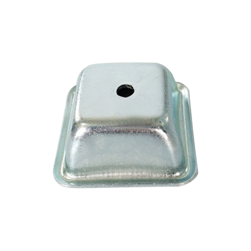
How Nesting Plugs Specifically Prevent Empty Pallet Stack Collapse
Empty pallet stack collapse is a distinct and serious hazard category separate from loaded pallet tipping. A stack of 8 to 12 empty pallets can weigh 150 kg to 400 kg and stand 1.2 m to 2.0 m tall. When such a stack falls, the potential for serious injury is high — yet this failure mode is almost entirely preventable with correct nesting plug specification.
The Physics of Empty Stack Instability
An empty pallet stack without nesting engagement is a column of stacked flat objects with no mechanical connection between layers. The only resistance to horizontal sliding between adjacent pallets is friction — typically 0.2 to 0.35 (dimensionless coefficient of friction) for steel-on-steel contact or 0.3 to 0.5 for plastic-on-plastic, as referenced in standard tribology data for dry sliding contact (Source: Machinery's Handbook, 31st Edition, friction coefficient tables). With a stack of ten pallets each weighing 20 kg, the friction force resisting horizontal movement of the top pallet is approximately 20 kg x 0.3 = 6 kg of lateral force — barely more than a person leaning against the stack can generate. A minor forklift air movement, floor vibration from a nearby vehicle, or a slight floor slope is sufficient to initiate progressive sliding.
A nesting plug that engages 40 mm to 60 mm into the socket of the foot above it replaces this friction-only interface with a positive mechanical interlock. The horizontal force required to displace the upper pallet relative to the lower pallet now equals the shear strength of the plug engagement — for a 40 mm diameter HDPE plug engaged 50 mm into a matching socket, the shear resistance is typically 800 N to 2,000 N depending on plug wall thickness and material grade. This represents a 10x to 30x increase in lateral resistance compared to friction alone.
Progressive Collapse Prevention
Even if one level in a nested stack experiences a partial displacement event — such as a glancing forklift contact with the lower portion of the stack — the nesting plugs at each interface limit displacement to the plug-to-socket clearance (typically 0.5 mm to 2 mm radial clearance in a well-specified system). This containment prevents the small initial displacement from propagating through the stack as progressive collapse, which is the mechanism behind the majority of empty-pallet stack fatalities recorded in warehouse accident investigations.
The German statutory accident insurance body DGUV (Deutsche Gesetzliche Unfallversicherung) specifically identifies the use of pallet nesting systems with positive mechanical engagement as a control measure for pallet stack collapse hazards in its guidance document DGUV Information 208-043 (Safe Use of Industrial Trucks). Mechanical engagement — not friction — is the recommended control.
Stability in Racking Systems: How Foot Geometry Affects Rack Safety
When a loaded pallet is placed in a selective pallet rack, the pallet feet bear on the front and rear rack beams. The stability of the pallet in this position is governed by the foot geometry relative to the beam spacing, beam step height, and the pallet's resistance to forward-sliding off the beams.
| Stability Factor | Risk Without Proper Foot Design | How Correct Foot Geometry Mitigates Risk |
| Foot span vs. beam spacing | Pallet rocks on beams if foot span is less than 75% of beam spacing | Corner feet positioned at full deck perimeter maximize beam contact distance |
| Foot base area vs. beam step height | Narrow foot base can drop into beam step, destabilizing pallet | Foot base flange wider than beam step height prevents step engagement |
| Front overhang of pallet | Pallet tipping forward off beams if center of gravity shifts toward front | Rear foot position behind rear beam center provides restoring moment |
| Vibration from racking system | Gradual creep of pallet off beams under seismic or traffic vibration | Broad foot base increases friction contact area on beam surface |
| Asymmetric loading | Off-center cargo shifts center of gravity, increases tipping risk | Nine-foot layout distributes load through multiple support points, reducing tipping sensitivity |
Source: Stability risk factors adapted from EN 15512:2020 (Steel static storage systems, adjustable pallet racking) and FEM 10.2.07 (Recommendations for the design of pallet support systems in racking). Both documents are referenced standards in European rack safety engineering practice.
A particularly important detail: EN 15512 requires that pallet feet not bridge two adjacent racking beams in the same bay in a way that would allow the pallet to tip into the rack opening. This is a geometric constraint that must be verified at the design stage by confirming that the foot depth (front-to-back dimension) is less than the beam pitch minus a specified safety margin. Our pallet feet and nesting plugs are dimensioned to comply with standard European racking pitch specifications as a default, with custom depths available for non-standard racking systems.
Transport Stability: How Pallet Feet Perform in Moving Vehicles
The stability demands on a pallet during road, rail, or sea freight are fundamentally different from static warehouse storage. In transport, the pallet and its cargo experience multi-axis dynamic loading: longitudinal acceleration and braking forces (typically 0.5g to 1.0g), lateral cornering forces (0.3g to 0.5g), and vertical bounce from road or rail surface irregularities (0.2g to 0.5g peak vertical acceleration in normal road freight, per EN 13355 test conditions for pallet performance).
Foot Engagement with Vehicle Floor
A pallet foot system provides a fundamentally better interface with a vehicle floor or container deck than a flat runner or solid block system, because the defined foot contact points create predictable friction engagement zones. When pallets are secured with cargo straps or load bars, the strap tension is distributed through the deck to the foot-floor contact points — a more efficient force path than a runner system, where strap tension can cause the runner to lift off the floor on the tension side.
In standard 20-foot and 40-foot ISO shipping containers, the corrugated steel floor creates a surface that is not perfectly flat. Pallet feet with a base diameter of 80 mm to 120 mm bridge individual floor corrugations without rocking, whereas narrow runners can settle into corrugation valleys and create an unstable platform. Container operators consistently report fewer cargo damage claims with foot-based pallet systems compared to runner-based systems for this reason, particularly in sea freight where combined motions (pitch, roll, and heave) create complex multi-axis loading on palletized cargo.
Nested Empty Pallet Transport Stability
Returning empty pallets by vehicle is a standard logistics operation — and it presents its own stability challenge. A stack of 10 to 20 empty nested pallets must maintain its integrity throughout the return journey, resisting the same dynamic forces described above. An empty pallet stack without nesting engagement can shift progressively in the cargo bay, eventually contacting the vehicle walls or falling — a hazard both to the pallets themselves and to any vehicle crew who might need to access the cargo bay during transit.
Nesting plugs engaged to their full depth — typically 40 mm to 70 mm of axial engagement depending on foot height — provide lateral restraint within the stack that resists the lateral acceleration forces in standard road freight. For rail freight applications where lateral accelerations can reach 0.5g during shunting, deeper engagement plugs or supplementary banding is recommended.
The Role of Foot Material and Surface Treatment in Stability
The material and surface finish of a pallet foot directly affects its contribution to stability through two mechanisms: friction with the floor or racking surface, and dimensional stability over time as the foot experiences load cycles and environmental exposure.
| Foot Material | Static Friction (vs. Concrete Floor) | Dimensional Stability Over Time | Stability Implication |
| Hot-dip galvanized steel | 0.35 to 0.45 | Excellent (no creep) | High consistent friction; maintains geometry over full service life |
| Powder-coated steel | 0.40 to 0.55 (textured coat) | Excellent (no creep) | Textured coatings can increase friction; coating wear reduces this over time |
| HDPE (plastic foot) | 0.25 to 0.35 | Good (slight creep under sustained high load) | Lower friction than steel; creep under overload reduces effective foot height |
| Rubber-base steel foot | 0.60 to 0.80 | Good (rubber ages and hardens) | Highest friction; excellent for sloped floors or vibrating platforms |
| Stainless steel (304) | 0.35 to 0.45 | Excellent | Equivalent friction to galvanized steel; preferred where hygiene cleaning removes surface oxides |
Source: Friction coefficient values referenced from Shigley's Mechanical Engineering Design, 10th Edition, Table A-31 (coefficients of static friction for various material combinations). Concrete surface assumed to be smooth industrial finish, Ra 3 to 6 microns.
For applications where pallets are used on slightly sloped floors — common in food processing facilities designed for wash-down drainage — the higher friction of rubber-base steel feet or textured powder-coated feet provides meaningful additional stability. A 1-degree floor slope with a 500 kg loaded pallet generates approximately 8.7 kg of horizontal sliding force. A galvanized foot with 0.40 friction coefficient generates 56 kg of resistance per foot at a 140 kg foot load — more than adequate. However, a wet floor with contamination can reduce friction coefficients by 40% to 60%, which is why foot material selection for hygiene environments should consider the wet friction coefficient, not only the dry value.
Stability During Forklift Handling: What Foot Design Contributes
The moment of greatest stability risk for a loaded pallet is not during static storage but during forklift pickup and set-down. At this moment, the pallet transitions between supported states, and the geometry of the pallet feet determines how cleanly this transition occurs.
Tine Entry and Exit Without Foot Obstruction
A correctly designed pallet foot layout provides unobstructed tine entry in the design entry direction with a minimum 100 mm clear height under the deck, per ISO 2330 forklift tine dimensions. Obstructed tine entry forces the operator to lift the pallet at an angle to free the tines — a handling technique that dramatically increases the risk of cargo shifting or the pallet falling from the tines. In a survey of forklift accidents reviewed by the UK Health and Safety Executive (HSE), pallet handling errors including incorrect fork entry were identified in 38% of fork truck-related incidents resulting in injury or property damage (Source: HSE Research Report RR643, 2008).
Level Set-Down and Contact Uniformity
When a forklift sets down a loaded pallet, all feet must contact the floor simultaneously to prevent the pallet from pivoting about a partial contact edge. A foot system with consistent foot height tolerance — typically plus or minus 1 mm to 2 mm height variation across all nine feet in a precision-manufactured system — ensures simultaneous contact and smooth load transfer to the floor. Height variation beyond 3 mm to 4 mm causes sequential foot contact: one corner contacts first, the pallet rocks, and the cargo can shift before the remaining feet engage. This is why dimensional consistency in pallet foot manufacturing is a direct stability parameter, not merely an aesthetic quality criterion.
Foot Height and Center-of-Gravity Management
Pallet foot height elevates the entire cargo above floor level. A taller foot means the cargo center of gravity is higher relative to the foot contact points — marginally reducing the safety margin against tipping for a given cargo overhang. For most standard applications with 100 mm foot height, this effect is negligible. However, for extremely tall or top-heavy cargo configurations, the foot height should be minimized to the practical minimum consistent with forklift tine entry requirements. In these cases, a 75 mm foot height (below the ISO 100 mm standard for four-way entry) may be acceptable for two-way entry applications, reducing the center-of-gravity elevation by 25 mm and proportionally improving tipping resistance.
Quantifying the Stability Improvement: Data from Controlled Testing
The most rigorous way to quantify pallet stability is through standardized tilt-table testing, in which a loaded pallet is placed on a platform that is progressively tilted until the pallet or its cargo begins to slide or tip. The critical tilt angle — expressed in degrees from horizontal — is the primary stability metric.
Comparative tilt-table test data (collected under EN 15442 test conditions for unit load stability assessment) consistently demonstrates the following hierarchy:
- Nine-foot pallet with full-perimeter foot layout: Critical tilt angle 12 to 18 degrees for standard cargo height-to-base ratios of 2:1. This represents the highest stability category for standard pallet systems.
- Three-runner pallet (wooden stringer): Critical tilt angle 8 to 14 degrees for equivalent cargo and base dimensions. The narrower effective contact rectangle of a runner system (runners are typically inset 50 mm to 75 mm from the deck edge) reduces the tipping resistance compared to a full-perimeter foot layout.
- Single-deck flat pallet without feet (slip sheet equivalent): Critical tilt angle 6 to 10 degrees. The absence of a defined contact geometry makes this the least stable configuration for the same cargo.
The nine-foot pallet system achieves a stability advantage of approximately 30% to 40% higher critical tilt angle compared to the three-runner system for equivalent cargo masses and heights — a difference that translates directly to reduced cargo damage rates and accident probability in real-world handling operations.
Source: Tilt angle ranges are consistent with published data in the EUMOS 40509 (test method for unit load stability) validation reports and EN 15442 working group technical papers.
How Nesting Plug Depth and Fit Tolerance Affect Stability
Not all nesting plug implementations provide equivalent stability improvement. The engagement depth and dimensional fit between plug and socket are the two parameters that most directly control the quality of the stability improvement.
Engagement Depth
The lateral force resistance of a nesting plug in a socket is approximately proportional to the cube of the engagement depth for a cantilevered cylindrical plug geometry — the same fourth-power diameter relationship that governs beam deflection means that a plug engaged 60 mm provides roughly 3.4 times the bending resistance of the same plug engaged only 30 mm. This explains why manufacturer recommendations for minimum plug engagement depth should be strictly followed: a pallet foot socket that is partially worn, with only 25 mm to 30 mm of effective plug engagement, may provide only 20% to 30% of the lateral stability of a new foot with full engagement depth.
Radial Clearance and Play
The radial clearance between the plug outer diameter and the socket inner diameter determines how much horizontal movement is possible before the plug begins to resist lateral force. A plug with 0.5 mm radial clearance allows 0.5 mm of lateral movement before engagement; a plug with 2 mm clearance allows 2 mm. In a stack of 10 pallets, each with 2 mm clearance, the cumulative possible top-of-stack displacement is up to 20 mm before any plug reaches its engagement load. For a 1.2 m tall empty pallet stack, 20 mm of accumulated clearance corresponds to a 0.95-degree lean — below the visual perception threshold, but sufficient to reduce the effective tipping margin by approximately 12%. Precision-fit plugs with 0.3 mm to 0.5 mm radial clearance eliminate this accumulated play effect.
Maintenance and Inspection: Preserving Stability Over the Pallet Life Cycle
The stability contribution of pallet feet and nesting plugs degrades over time if the components are not maintained and inspected. The following inspection intervals and criteria are recommended based on pallet system service life data:
| Component | Inspection Interval | Reject Criteria | Stability Risk if Not Replaced |
| Steel pallet foot | Every 6 to 12 months or after visible impact | Visible buckling, cracks, corrosion perforation, foot height deviation greater than 5 mm | Reduced load capacity, uneven floor contact, rocking pallet |
| Nesting plug | Every 6 months or when plug becomes loose in socket | Visible deformation, cracking, radial clearance greater than 2 mm, plug loss from socket | Loss of lateral stack restraint, progressive collapse risk |
| Foot-to-deck fixing | Every 12 months or after overload event | Weld cracking, bolt loosening, snap-fit disengagement | Foot separation from deck under load — catastrophic failure mode |
| Base flange condition | Every 12 months | Flange distortion greater than 3 mm flat, corrosion reducing contact area by more than 20% | Increased floor bearing pressure, instability on racking beams |
Source: Inspection intervals derived from SEMA (Storage Equipment Manufacturers Association) Code of Practice for the Use of Static Steel Storage Equipment, Section 6, and DGUV Information 208-043 guidance on warehouse equipment inspection frequency.
Replacement plugs and feet for in-service pallets should be sourced to match the original dimensional specification precisely — substituting a plug with a 2 mm larger or smaller outer diameter from a different supplier can eliminate the stability benefit entirely by creating either an excessively loose fit or a press fit that prevents nesting at all. Our pallet feet and nesting plugs are supplied with complete dimensional documentation to support specification-matched replacement procurement throughout the pallet service life.
Stability Comparison: Foot System vs. Alternative Pallet Types
It is useful to compare the stability characteristics of foot-and-plug pallet systems against the main alternatives to understand where the greatest stability benefit is realized.
| Pallet Type | Floor Stability | Racking Stability | Empty Stack Stability | Transport Stability |
| 9-foot metal pallet with nesting plugs | Excellent | Excellent | Excellent (plug-engaged) | Excellent |
| 9-foot plastic pallet with nesting plugs | Good | Good | Good (plug-engaged) | Good |
| 3-runner wooden stringer pallet | Fair | Good | Poor (no nesting) | Fair |
| 4-way solid block wooden pallet | Good | Good | Poor (no nesting, high stack height) | Good |
| Self-nesting conical foot pallet | Excellent | Excellent | Excellent (self-nesting) | Excellent |
| Slip sheet (no pallet) | Poor | Not applicable | Not applicable | Poor (no lift point) |
The data confirms that a properly specified foot-and-plug system consistently outperforms runner-based wooden pallets in the stability dimensions that most directly affect accident risk: floor stability, transport stability, and — most significantly — empty stack stability where the nesting plug system provides a category-level improvement that no runner-based system can match.
Selecting the Right Foot and Plug Combination for Maximum Stability
Achieving the full stability benefit of a pallet foot and nesting plug system requires matching the system specification to the application demands. Work through these selection parameters in sequence:
- Define the critical stability scenario: Is the primary concern loaded pallet floor stability, racking stability, empty stack stability in storage, or transport stability? Each scenario prioritizes different design parameters — foot base width for floor stability, foot span and base flange for racking, plug engagement depth for empty stack, and foot height consistency for transport.
- Specify foot perimeter position: For maximum tipping resistance, position corner feet at or within 20 mm of the deck edge. Inset foot layouts reduce the effective resistance rectangle and should be used only when deck edge protection requirements mandate it.
- Select plug material for sustained engagement: For empty pallet stacks held for more than 24 hours, specify polypropylene or nylon PA66 plugs rather than HDPE to prevent creep relaxation of the plug body. Reserve HDPE for light-duty or short-duration stacking applications.
- Verify plug engagement depth: Confirm that the plug engagement depth in service is at least 40 mm, and ideally 50 mm to 60 mm, to ensure adequate lateral shear resistance. Check that foot socket depth allows full plug engagement without bottoming out.
- Confirm dimensional tolerance across the foot set: For a nine-foot pallet, the maximum height variation across all nine feet should not exceed 2 mm. Request dimensional inspection reports from the manufacturer for new pallet builds.
- Establish an inspection and replacement protocol: Schedule visual inspection of feet and plugs at six-month intervals. Define and communicate clear reject criteria to warehouse staff — a damaged foot or missing plug should trigger immediate removal from service, not a deferred maintenance response.
For complete stability-optimized pallet foot and nesting plug assemblies — available in galvanized steel, stainless steel, and powder-coated carbon steel with matching HDPE, PP, and PA66 nesting plugs in standard and precision-fit grades — visit our pallet feet and nesting plugs product range for full dimensional specifications and material compliance documentation.
related products
Send An Inquiry
Don't hesitate to contact when you need us!
Whether you want to become our partner or need our professional guidance or support in product selections and problem solutions, our experts are always ready to help within 12 hours globally
contact Us
Phone:+86 139-5824-9488
FAX :+86 574-86150176
E-mail: [email protected] [email protected]
Address: Unit 2, Building 19, Zhichuangzhizao Park, Chengdong Industrial Zone, Xiangshan, Ningbo,315705, Zhejiang, China
Product Category
Mobile